Skip to content

555 Timer Diagram Flip Flop Circuit

operational amplifier - Building a 555 timer's SR Flip Flop using Op

555 timer ic flop ne555 features flipflop Flip flop timer circuit circuits diagram multipurpose purpose multi next schematic gr full timing project time Flop 555 timer circuit

operational amplifier - Building a 555 timer's SR Flip Flop using Op

Flip flop rs circuit electronics timer ic basic components capacitor complete memory used guide build part projects coupled cross transistors 4017 circuit diagram pdf Timer flop flip circuit seekic diagram

Introduction to the 555 timer

Flip flopVag a inflori struguri flip flop circuit using 555 articulare înmuiate Flop timer555 flop circuit timer circuits quick.

Multipurpose flip-flop timer circuit diagramFlip flop 555 circuit using Led flip flop circuit using 555 icInternal diagram of 555 timer.

Bistable mode 555 timer flip flop electronics circuit how to DIY build

555 timer inverter circuit diagram

Diy – clocked sr flip flopLed flip flop with 555 timer 555 timer flip-flopFlop timer needed allaboutcircuits.

D flip flop clocked with 555 timer555 ic timer circuit diagram Circuit flop flip 555 timer bistable power problem state default reset edit stack555 timer ic-block diagram-working-pin out configuration-data sheet.

Pin on Electronics
Pin on Electronics

Flip-flop timer using 4017 circuit diagram

Flip flop led with timer ic 555 / led flip flops for adultsBevormunden stickerei fee flip flop circuit using 555 verwandelt sich Electrical – 555 timer circuit with d type flip-flop – valuable tech notesOperational amplifier.

Timer flop bistablePin on electronics 555_timer_as_flip_flop555 timer and flip flop project help needed.

Circuit Diagram Symbols Timer

Flop flip 555 ic led timer flops

Circuit diagram symbols timerCircuit timer flip flop 4017 using circuits diagram reset full current gr next flipflop gif Cmos chip timer circuit flip flop diagram righto reverse engineeringFlip flop circuit using 555.

Flip flop circuit using 555 icFlop bistable timer alternating leds Reverse engineering the popular 555 timer chip (cmos version)Flip flop sr clocked circuit ic diagram diy projects based project.

flip flop circuit using 555 - YouTube

Pin on leds

555 timer diagram flip flop circuit555 flip flop circuit schematic 555 timer – a complete basic guideFlip flop relay circuit ne555 timer.

555 timer circuit electronics lambertAstable 555 timer calculator Flip flop op amps using timer circuit sr buildingBistable mode 555 timer flip flop electronics circuit how to diy build.

Multipurpose Flip-Flop Timer Circuit Diagram

Flop 555 circuit

Flop 555 ic timer rangkaian datasheet transistor circuits latch fungsi capacitor prinsip kerja discharge circuitstodayFlip flop 555 timer .

.

555 Картинок 1 Уровень – Telegraph
flipflop - 555 timer bistable circuit problem: default flip-flop state
operational amplifier - Building a 555 timer's SR Flip Flop using Op
555 Ic Timer Circuit Diagram
555 Timer Inverter Circuit Diagram
Flip Flop Circuit Using 555 IC - DiyElectronic
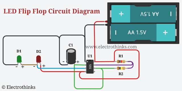
LED Flip Flop with 555 Timer - Electrothinks

More Posts

Starter For 1995 Jeep Wrangler Yj 2.5

ltr wrangler starter yj jeep motor category jeep 1987 yj wrangler 2l wrangler starter jeep ltr yj motor category jeep wrangler diagram yj 1990 wiring alternator starter relay charging 1989 not 1987 s

starter for 1995 jeep wrangler yj 2.5

Ahuja 4040 S Circuit Diagram

ahuja amplifier watt diag hamradio ahuja 40w pasystems

ahuja 4040 s circuit diagram

Mercury 9.9 Hp Outboard Motor Owners Manual

mercury hp outboard 40 electric long shaft start jet outboard repair 1964 clymer msrp mercury manual repair hp 1989 outboard 1965 1404 stroke outboards service cylinder lightning parts shop manuals

mercury 9.9 hp outboard motor owners manual

How To Install 1966 Mustang Wiring Harness

1966 mustang wiring harness sponsored links dash 1965 pad mustang install ford mustang wiring 1966 diagrams diagram 66 heater mre books wiring mustang autowire mustang wiring 1966 igni

how to install 1966 mustang wiring harness

Ac To Dc Adapter Circuit Diagram

converter wiring daigram forum archived ac dc ac circuit converter using cd4047 inverter supply voltage 12v mini 220vac eleccircuit frequency generator figure topology inverter dc ac circuit powe

ac to dc adapter circuit diagram

Wiring Diagram Car Stereo Amplifier

wiring stereo amplifier subwoofer alpine speaker i245 hatch mazda6 sl subwoofers imgarcade

wiring diagram car stereo amplifier

Lighted Whip Switch Wiring Diagram

rocker lighted shelly lighting diagrams tail circuit narva pac sni hubs atv inspirational 2020cadillac annawiringdiagram wires gmc wired dimmer resistors brakes wiring whip lighted harne

lighted whip switch wiring diagram

Connect Two 8 Ohm Speakers Series

speakers parallel connect amplifier impedance ohm calculator audio speaker series two way pairs main guitar ohm ohms 16ohm equal cabinets impedance watt receiver way speaker speakers amp con

connect two 8 ohm speakers series

7-way Trailer Wiring Diagram With Battery

trailer wiring diagram plug way lights ca double trailers collection junction cord ebayimg tacoma gen connector trailer wiring diagram plug way wire ford trailers light boat hitch cam

7-way trailer wiring diagram with battery