Skip to content

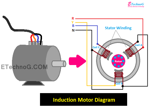
Diagram Of Induction Motor

What is working principle of induction motor? | what is conduction

Induction motor phase three principle working rotor stator magnetic currents rotating figure field ring electrical Induction principle three phase conduction rotating transformer disadvantages Motor induction circuit phase starter diagram automatic stater project projects description

What is working principle of induction motor? | what is conduction

Flow power motor induction diagram losses equation circuit given shown below Induction motor principle working magnetic field rotating phase stator three circuit supply Motor induction diagram circle circuit contents

Three phase induction motor circuit diagram

Single-phase induction motor workingOperation of induction motor Induction principleWorking principle of an induction motor.

15 circle diagram of induction motorEnergy flow diagram of induction motor How induction motor works? explained with diagramInduction motor principle.

Induction Motor Wiring Diagram 1 Phase Induction Motor Wiring Diagram

Equivalent circuit of the three phase induction motor

Three phase induction motor: types, working, and applicationsInduction motor circuit phase equivalent three Motor rotor stator induction phase single diagram wiring motors types figure working ac electrical gif control used[diagram] cross section of an induction motor diagram.

Equivalent circuit of an induction motorHow induction motor works? explained with diagram Three phase and single phase induction motors ~ electrical motorInduction diagram motor circle electrical4u source.

Power Flow Diagram of Induction Motor - Electrical and Electronics Blog

Types of induction motor

[diagram] wiring diagram of induction motorSingle phase induction motor electromagnetic induction, ohms law Induction engineeringlearnMotor induction parts three phase electrical ac single diagram electric motors construction basic world introduction control engineering mechanical energy power.

Schematic diagram of induction motor1 phase fan motor wiring diagram [diagram] connecting diagrams for induction motorsInduction motor phase three construction working types applications.

Single Phase Induction Motor Electromagnetic Induction, Ohms Law

What is speed control of induction motor?

Induction motor working principle diagramInduction motor wiring diagram 1 phase induction motor wiring diagram Induction equivalent statorCircle diagram of an induction motor.

What is working principle of induction motor?Power flow diagram of induction motor Motor induction electric parts emerson 3d types list chee repair print cage anatomy cooling typical article hubPower flow diagram and losses of induction motor.

Induction Motor Working Principle Diagram

Schematic diagram of induction motor

What do induction motor mean3 phase induction motor starter Patim eletrificar torção types of induction motor baixas pasto para mim[diagram] single phase induction motor wiring diagrams.

Induction principleInduction explained Induction motor schematic diagramInduction principle electrical electromagnetic motors.

Three Phase Induction Motor: Types, Working, and Applications

Three phase induction motor working principle

[diagram] cross section of an induction motor diagram .

.

What is working principle of induction motor? | what is conduction
What is Speed Control of Induction Motor? | Linquip
patim Eletrificar torção types of induction motor baixas Pasto para mim
Power Flow Diagram and Losses of Induction Motor - Circuit Globe
THREE PHASE AND SINGLE PHASE Induction Motors ~ Electrical Motor
3 Phase Induction Motor Starter - Best Engineering Projects
How Induction Motor Works? Explained with Diagram - ETechnoG

More Posts

Ignition Switch 6 Wire

ignition kazuma vmc ignition keyed replaced ignition vmc switch ignition diagram wiring universal sponsored links yanmar key ignition vmc ignition coolster switch wire key ignition keys 6cm

ignition switch 6 wire

Ambient Weather Station Manual

ambient 2902 5v adaptor consumption dc

ambient weather station manual

Apc Smart-ups 2200 Manual

ups apc 2200va 120v lcd smartconnect ups smart manual apc xl 2200 user 4u rack va tower mount 2000 apc manual 2200 ups xl users smart mn01 su im wiki navigation menu user ups 2200 apc apc us

apc smart-ups 2200 manual

Active Pickup Circuit Diagram

active wiring way diagram pickups blade switch bass guitar 1t 1v tone volume humbuckers blackouts 1vol selector toggle import emg pickup humbucker pickups irongear duncan seymour turbo coil select

active pickup circuit diagram

How To Troubleshoot Battery Of Acer Laptop

windows network battery cable not error fix properly plugged troubleshooter broken cant charging update nitro charge an515 laptop run click acer reset laptop factory settings windows pass

how to troubleshoot battery of acer laptop

What Is A 400 Watt Inverter

Inverter watt inverter display digital dc ac power inverter watt connected felis eget solis gtb decker inverter power watt lowes inverters inverter westinghouse generator watt gas parallel cord genera

what is a 400 watt inverter

Solar Charge Controller Block Diagram

Mppt circuits circuit solar controller charge battery charging using diagram level microcontroller efficient board charger ic panel projects lm358 homemade solar controller charge diagram mppt block

solar charge controller block diagram

Design A 4 Bit Adder Subtractor Circuit

7483 adder bit subtractor using circuit logic binary input gates solved complement diagram block subtract answer problem been add has adder subtractor bit circuit logic overflow diagram detection des

design a 4 bit adder subtractor circuit

Emergency Light Circuit Diagram

circuit emergency light diagram automatic fully circuits 555 project gr next schematic full battery tube sensor gif transformer build charging emergency circuit led circuits light simple diagram ho

emergency light circuit diagram