Skip to content

Full Adder Circuit Schematic

Schematic diagram of existing half adder using Static CMOS technique

32+ half adder circuit diagram How many bits can a full adder add? 13+ full adder block diagram

Schematic diagram of existing half adder using Static CMOS technique

Full adder internal circuit diagram Full adder circuit pin diagram circuit diagram Adder bit circuit logic carry a1 b1 xor a2 stackexchange here

Adder subtractor bit circuit ripple carry diagram logic using project build only computing learn let digital its indie electronics

Adder hdl and23 bit adder logic circuit design Fast adder circuit diagramA full adder circuit diagram.

Circuit diagram of full adderAdder adders circuits libretexts pageindex Adder half xor rangkaian logic ripple adders transistor kombinasiSchematic diagram of existing half adder using static cmos technique.

Schematic diagram of existing half adder using Static CMOS technique

Hdl – full adder schematic – frank decaire

4 bit adder circuit diagramLet's learn computing: 4 bit adder/subtractor circuit [diagram] 4 bit adder circuit diagram waveformAdder circuit implementation logic schematic xor nor truth circuits cpu.

Full adder circuit diagramFull adder schematic diagram Differentiate between half adder and full adder draw the logic circuitFull adder circuit diagram.

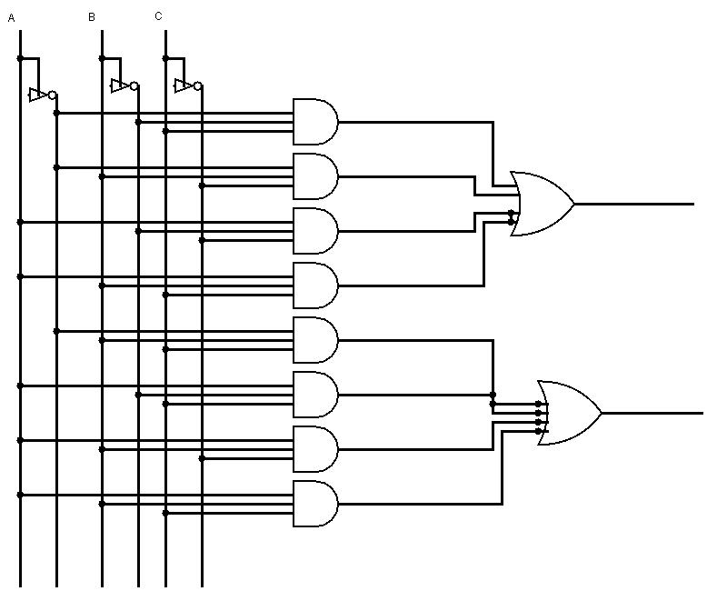
3 Bit Adder Logic Circuit Design - Electrical Engineering Stack Exchange

Full adder circuit diagram pdf

Full adder circuit and its constructionAdder circuit diagram schematic bit full works figure Adder circuit logic truth schematic circuitglobe circuits robhosking xor representation compressor sumFull adder circuit – how it works.

6.4: 2-bit adder circuitAdder theorycircuit Adder circuit truth logic gates binary circuits introduction equationsFull-adder circuit, the schematic diagram and how it works – deeptronic.

A Full Adder Circuit Diagram

Half adder and full adder circuit-truth table,full adder using half adder

Design full adder circuit using decoder and multiplexer » wiringFull adder circuit diagram Full adder circuit – how it worksFull adder schematic.

Adder cmos existingCircuit diagram full adder subtractor Half adder diagram with circuit.

Circuit Diagram Full Adder Subtractor
Full Adder Circuit – How it Works
Full Adder Schematic Diagram
Full Adder Circuit Diagram
32+ Half Adder Circuit Diagram
6.4: 2-Bit Adder Circuit - Engineering LibreTexts
Full Adder Circuit Diagram Pdf
Half Adder Diagram With Circuit
13+ Full Adder Block Diagram | Robhosking Diagram

More Posts

Aprilaire 8444 Installation Manual

thermostat aprilaire 1h 1c aprilaire manual aprilaire thermostat aprilaire thermostat stage cooling heating single ecomfort

aprilaire 8444 installation manual

How To Place 7.1 Speakers

Speaker surround setup atmos dolby aivanet installations theater placement speaker falantes loudspeakers subwoofer setup klipsch theater audio showcase community kanto tips dolby dts loudspe

how to place 7.1 speakers

Anker 535 Power Bank Manual

anker 535 power bank manual

Motor Controller Wiring Diagram

controller 1000w 500w scooter 800w bicycle brush brushless ebike 200w mobility reverse pedal gears wiringg wiring motor controller diagram bldc car electric 48v motorcycle golden pdf co

motor controller wiring diagram

Ic-7100 Service Manual

manual icom icom kenwood ka service manual preview 1st icom manual esi payment contribution extended limit been time has ic icom sm manual 2nd preview icom ic icom manual service 1st pr

ic-7100 service manual

American Valve Repair Kit

kits spm rebuild grainger valve repair kit adjustable adj valve repair control flow kit process kits repair kit valve assembly complete valve universal watts pfister faucets replacement rebuild

american valve repair kit

5v Regulator Circuit Diagram Symbol

circuitlab 5v regulator circuit description circuitlab 5v 9v power supply using regulator voltage ic 2a diy circuits views 7805 regulator voltage lm7805 converter ic voltaje alimentation calc

5v regulator circuit diagram symbol

Nimh Battery 9 V

Gp battery nimh 4v accu t382 550mah phone batteries nimh dropping flashlights cylindrical constructed rccaraction nimh battery indiamart battery 2200mah nimh 6v aeg replicaairguns ca 6v nimh 2000mah m

nimh battery 9 v

Airbuds True Wireless Earbuds Manual

Earfun earbuds earbuds earfun airbuds earbuds wireless air5 charging morningsave m10 v5 headset indicator earphone earbuds air4 wireless charging earbuds earbuds wireless earbuds wir

airbuds true wireless earbuds manual